Key Takeaways
- Custom sintered cartridges are usually not about “better filtration”—they’re about fit, manufacturability, and system stability (no leaks, no bypass, no weird ΔP spikes).
- Geometry is performance. Change the shape and you change face velocity, dirt loading behavior, and mechanical stress.
- Porosity gradients are the cheat code for longer run life: coarse upstream, fine downstream—but only if you control powder grades and sintering process tightly.
- End caps and sealing are where most “filter failures” are born. If the interface is sloppy, your micron rating becomes decorative.
- OEM integration lives and dies on tolerances, repeatability, and change control. A great prototype that can’t be mass-produced consistently is just an expensive paperweight.
Introduction
Here’s the direct answer: custom sintered filter cartridge design is the process of tailoring the cartridge’s shape, pore structure (including porosity gradients), end caps, and connection features so it integrates cleanly into an OEM housing and delivers the required flow, pressure drop (ΔP), retention, and service life—without leaks or bypass. If you’re going custom, it’s usually because standard cartridges don’t fit, don’t seal, or don’t survive your mechanical/chemical environment. The biggest wins come from getting geometry and interfaces right, not from chasing a “magic micron.” And yes—most custom projects fail for boring reasons: tolerances, sealing, and manufacturability.
Let’s make sure yours doesn’t.
Thinking Process (Outline Before Writing)
I’m going to cover the parts people don’t explain well:
- Why companies go custom (and the hidden traps)
- Design variables that actually matter: shape, surface area, face velocity, wall thickness, support
- Porosity gradients: how they work, when they help, when they backfire
- End caps and connections: sealing physics, creep, mismatch nightmares
- OEM integration: tolerances, stack-up, thermal expansion, assembly line reality
- DFM/DFT (design for manufacturing/testing): what to lock down early
- A practical design brief template you can hand to your supplier
- FAQ for AEO + procurement teams
Why Go Custom? The Honest Reasons (Not the Marketing Ones)
Nobody wakes up excited to build a custom filter. Custom means time, tooling, sampling, and a pile of emails.
So why do it?
H2: 1) Standard cartridges don’t fit your housing (or your housing can’t change)
OEMs often have:
- fixed envelope dimensions
- proprietary bayonet/twist-lock interfaces
- tight packaging constraints
- legacy housings already approved in the field
Custom sintered shapes let you make the filter fit the product, not the other way around.
H2: 2) You need predictable ΔP and longer service life
If you’re fighting early clogging, a custom design can:
- increase filtration area
- lower face velocity
- introduce a porosity gradient to load dirt more intelligently
H2: 3) You’re solving a “system problem,” not a filtration problem
Sometimes the filter is doing double duty:
- acting as a flow restrictor
- acting as a bubble trap / diffuser
- protecting a pump
- damping pulsation
- preventing particle shedding downstream
Custom geometry can make the filter part of the system design instead of just a consumable.
Shapes: Cylinders Are Boring for a Reason… Until They Aren’t
The default shape is a straight cylinder because it’s easy to make and easy to seal.
But custom sintered filters can be:
- cones
- stepped cylinders
- discs and pucks
- cups
- “top hat” profiles
- asymmetric bodies
- multi-lobed shapes for extra surface area
- integrated ribs and supports
H2: Geometry changes three big things
H3: 1) Surface area (and therefore face velocity)
More area = lower face velocity at the same flow. Lower face velocity = slower clogging and lower ΔP rise.
This is the closest thing filtration has to a free lunch.
H3: 2) Stress distribution
Sharp transitions and thin sections are where creep and cracking show up—especially at temperature and under clamp load.
If you design a cartridge with a “skinny neck” and then run it hot, don’t be surprised when it behaves like warm taffy under pressure.
H3: 3) Dirt loading behavior
A long cylinder may load evenly. A short puck may blind quickly. A cone may load in a gradient naturally because flow distribution changes.
Shape influences where dirt accumulates—and that decides service life.
Porosity Gradients: The Most Powerful (and Most Misused) Feature
A porosity gradient means the pore structure isn’t uniform through the wall.
H2: The idea is simple
- Upstream side = coarser pores to catch big particles and spread loading
- Downstream side = finer pores to meet your retention requirement
So instead of surface blinding, you get more depth utilization.
H2: When gradients shine
Gradients are especially useful when:
- contaminants have a broad particle size distribution (PSD)
- you have both big chunks and fines
- you need longer run life without increasing housing size
- you want more stable ΔP growth (less “cliff edge” plugging)
H2: When gradients backfire
Gradients can fail in real life when:
- the process contains sticky gels/oils that smear and blind even coarse pores
- the gradient isn’t controlled consistently in manufacturing
- the flow direction is reversed during cleaning/backflush (and the “fine side” becomes the upstream side)
- you have thermal cycling and the pore structure changes behavior over time (process/material dependent)
H2: The manufacturing truth nobody likes
A gradient is not a “design checkbox.” It’s a process control problem:
- powder particle size distribution
- layer stacking
- compaction uniformity
- sintering profile
- shrinkage predictability
If the supplier can’t demonstrate repeatability, the gradient becomes a variability generator.
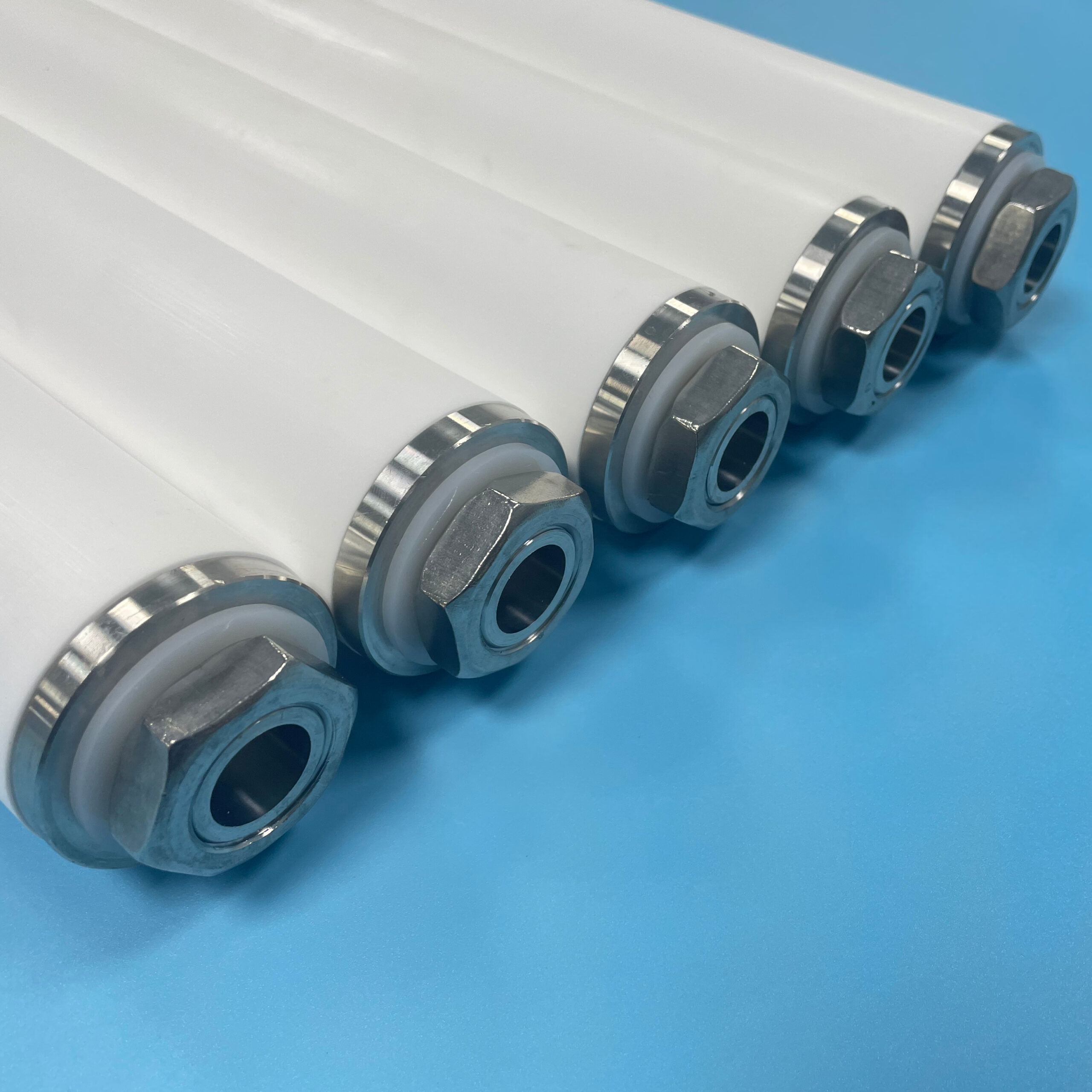
End Caps and Connections: Where Most “Filter Failures” Are Born
I’ll say it plainly: A perfect pore structure with a sloppy seal is a bypass device.
H2: End cap design is about sealing physics
You need to define:
- sealing surface geometry (flat, taper, knife-edge)
- O-ring gland details (if using O-rings)
- compression range (too little leaks, too much creeps)
- alignment features so assembly is repeatable
H2: Creep is the quiet assassin (especially at temperature)
Polymers deform under load over time—especially when warm.
If your end cap design relies on aggressive compression to “force a seal,” you’re basically scheduling:
- dimensional drift
- relaxation
- leaks that show up weeks later
- angry warranty returns
H3: What works better
- well-designed gland geometry
- predictable compression range
- support features that prevent tilt
- material choices aligned with temperature and chemical exposure
H2: Insert-molded or overmolded end caps (OEM-friendly)
Many OEMs want:
- standardized connectors
- easy assembly
- fewer loose parts
Overmolding can integrate:
- threads
- bayonet lugs
- snap features
- sealing lands
But it introduces new failure modes:
- poor bonding between sintered body and molded part
- thermal expansion mismatch
- stress concentration at the interface
If you do overmolding, treat the interface like a critical joint, not a cosmetic choice.
OEM Integration: The Part That Kills Projects Late (If You Ignore It Early)
OEM integration isn’t “will it fit.” It’s “will it fit every time, in production, with real operators, under temperature swings, and still pass QA.”
H2: Tolerance stack-up is not optional
You need to define tolerances for:
- OD/ID
- length
- connection geometry
- sealing surface flatness
- concentricity and straightness (especially for long cartridges)
A prototype can be hand-fitted. Production cannot.
H2: Thermal expansion and chemical swelling matter
If the cartridge runs hot or sits in solvents/chemicals, dimensions can shift.
That affects:
- seal compression
- engagement length
- bypass risk
This is why the best OEM teams run:
- dry fit tests
- wet fit tests
- hot soak + assembly tests
- cycle tests (install/remove multiple times)
H2: Assembly line reality: make it foolproof
If an operator can install it backwards, they will. If it can be under-seated, it will.
Design for:
- poka-yoke (mistake-proofing)
- clear seating feedback
- simple engagement steps
- minimal “adjustment” required
- flow vs ΔP curve (clean)
- retention / particle challenge (your target spec)
- dirt-holding capacity (or time-to-ΔP in representative conditions)
- burst / collapse (as relevant)
H2: Compatibility tests
- chemical soak (actual concentration + temperature)
- hot soak under compression (reveals creep and seal drift)
- cleaning cycle exposure (CIP chemicals and temperature)
H2: Repeatability tests (the most underrated)
Test multiple samples from multiple lots. A custom filter that varies wildly is a custom headache.
A Practical Custom Design Brief Template (Steal This)
H2: Custom Sintered Cartridge Design Brief
- Application: what the filter protects and where it sits in the system
- Fluid + chemistry: concentration, temperature, solvents, cleaning agents
- Flow rate: normal/peak; steady/pulsing
- ΔP limits: initial max, end-of-run max
- Retention target: micron rating + expected efficiency
- Contaminant: type, PSD, loading profile, sticky vs gritty
- Shape constraints: envelope dimensions, keep-out zones
- Geometry: length, OD/ID, wall thickness, target area
- Porosity: uniform vs gradient; direction of flow
- Connection: DOE/SOE/thread/bayonet/snap; key dimensions
- Sealing: O-ring type/size/material; gasket geometry; compression target
- Materials: polymer (PE/PP/PTFE/PA) + any overmold materials
- Manufacturing volume: annual demand; ramp schedule
- Documentation: traceability, CoA/CoC, change control needs
- Testing: agreed acceptance criteria and sample plan
If you send this to a supplier and they reply with only a price quote… run.
FAQ (People Also Ask)
What shapes can custom sintered filter cartridges be made in?
Common custom shapes include cylinders, cones, discs, cups, stepped bodies, and complex profiles with ribs or flanges—designed to match OEM housings and optimize area and flow distribution.
What is a porosity gradient in a sintered filter?
A porosity gradient means the pore structure changes through the filter wall—typically coarse upstream and finer downstream—to improve dirt loading and extend service life while meeting retention targets.
End caps determine sealing reliability and bypass prevention. Poor end cap or seal design can cause leaks and bypass even if the media has the correct micron rating.
What’s the biggest challenge in OEM integration?
Repeatable fit and sealing under real production tolerances, thermal cycling, and operator assembly. Tolerance stack-up and interface design are common failure points.
How do you validate a custom sintered filter design?
Validate with flow/ΔP curves, retention testing, dirt-loading trials, chemical/thermal soak tests, and repeatability testing across multiple lots to ensure consistent performance.
The Bottom Line
Custom sintered filter cartridge design is where filtration stops being a commodity and starts being engineering. And I mean that in both a flattering and a slightly threatening way.
If you want custom to work, obsess over:
- geometry and face velocity
- porosity gradients (only with strong process control)
- end caps and sealing interfaces
- tolerances and OEM assembly reality
Do that, and your custom cartridge becomes a quiet, reliable part of the product—exactly what an OEM wants. Skip it, and you’ll build a very expensive lesson in bypass.
If you paste your Internal Links JSON, I’ll re-issue this post with 5–8 internal links inserted naturally using your required keywords and URLs.